7. Mesh
The Mesh tree allows for defining global and local mesh settings, submitting and visualizing the resulting mesh.
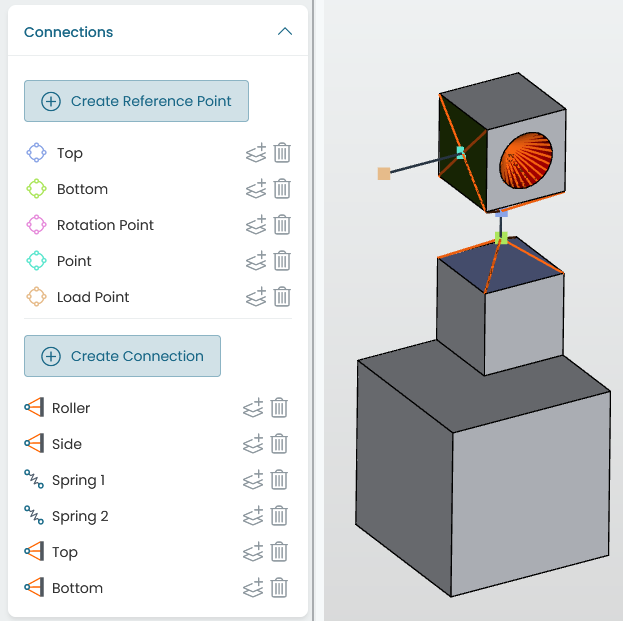
Fig. 7.1 Mesh tree
7.1. Global mesh settings
The Global mesh settings control the global mesh size using two parameters:
the global element size,
the number of elements per circle on curvature refinement.
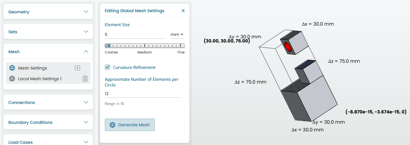
Fig. 7.2 Global mesh settings
The global element size is the target edge length of the generated elements. The final mesh lengths will be a normalized distribution of sizes around the requested size. It is possible that the native geometry limits the mesh size in regions where edges are smaller than the set value.
The curvature refinement refines curved surfaces so that the target number of elements per circle is close to the set value.
7.2. Local mesh settings
The “Add local settings” button on the Mesh tree allows the user to specify different mesh sizes on different volumes. This is especially useful when there are non-design volumes, which can have a lower mesh resolution than the design space volumes.
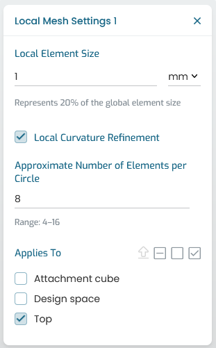
Fig. 7.3 Local mesh settings
The Local mesh settings contain the same parameters described above applied to specific volumes.
Note
The mesh engine features an automated small feature suppression setting, which is tuned (specifically for topology optimization) to ignore very small edges and / or slivers. The tolerance can be tuned further via the Model Editor, which may be helpful with challenging CAD assemblies.
7.3. Mesh results
The same Mesh tree allows for submitting and viewing the status of the mesh job. When complete, the resulting number of nodes and elements is presented.
The surface of the volume mesh can be made visible by toggling the Show Mesh selector of the Mesh results
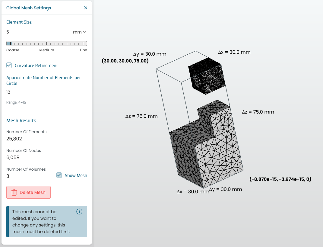
Fig. 7.4 Mesh results
The user should ensure that the mesh quality is appropriate for finite element analysis. The logs of the mesh job (accessible via the Jobs Monitor panel) will contain warnings regarding poor element quality and a summary quality report table as below:
Mesh quality report:
╔═══════════════════╦═══════╤═══════╤═════════╤═════════╤═══════╤═══════╤═══════╤═════════╗
║            Metric ║ Recom │ Recom │ Extreme │    Mesh │ Mesh  │ Below │ Above │ Above   ║
║                   ║   Min │ Max   │ Max     │     min │ max   │ recom │ recom │ extreme ║
║                   ║       │       │         │         │       │   min │ max   │ max     ║
╠═══════════════════╬═══════╪═══════╪═════════╪═════════╪═══════╪═══════╪═══════╪═════════╣
║      Aspect ratio ║     - │ 200   │ 1e+05   │    1.29 │ 15.5  │     - │ 0     │ 0       ║
╟───────────────────╫───────┼───────┼─────────┼─────────┼───────┼───────┼───────┼─────────╢
║        Edge ratio ║     - │ 200   │ -       │    1.05 │ 8.69  │     - │ 0     │ -       ║
╟───────────────────╫───────┼───────┼─────────┼─────────┼───────┼───────┼───────┼─────────╢
║   Volume skewness ║     - │ 0.9   │ -       │ 0.00388 │ 0.998 │     - │ 628   │ -       ║
╟───────────────────╫───────┼───────┼─────────┼─────────┼───────┼───────┼───────┼─────────╢
║ Face vertex angle ║    15 │ 165   │ -       │    7.63 │ 161   │   617 │ 0     │ -       ║
╟───────────────────╫───────┼───────┼─────────┼─────────┼───────┼───────┼───────┼─────────╢
║    Dihedral angle ║     - │ -     │ -       │    5.26 │ 169   │     - │ -     │ -       ║
╚═══════════════════╩═══════╧═══════╧═════════╧═════════╧═══════╧═══════╧═══════╧═════════╝
The definition of these metrics is described in the following subsection.
Tip
Special attention is recommended for very small face angles (< 0.5deg) or very high ratios. These are typically driven by poor CAD, and sometimes it pays off to review and clean up the CAD to get a better quality input mesh.
7.4. Mesh quality metrics
7.4.1. Aspect ratio
Tetrahedral aspect ratio is defined as the ratio between the element’s longest edge length and shortest altitude.
7.4.2. Edge ratio
The edge ratio is defined as the ratio between the element longest and shortest edge lengths.
7.4.3. Volume skewness
Equivolume skewness is a non-dimensional parameters ranging from 0 (good) to 1 (bad/degenerate element), comparing the volume of the element with its optimal volume, given by
where
\(V\) is the element volume,
\(V_{\mathrm{opt}}\) is the ideal element volume given by \((8\sqrt{3}/27) {R_{\mathrm{cs}}}^3\)
\(R_{\mathrm{cs}}\) being the element circumsphere radius.
7.4.4. Face vertex angle
Face vertex angle considers the angle between intersecting edges of all element faces.
7.4.5. Dihedral angle
Dihedral angle considers the angle between intersecting faces of an element.