3. Geometry Upload
3.1. Geometry from CAD
The starting point of a topology optimization workflow is the definition of a CAD model which may comprise several parts (volumes, solids, bodies) or a single component. In both cases we also need to define at least one design space (DS) volume.
This input CAD must comprise solid geometry (volumes in Möbius) in Parasolid or STEP format, respecting the following criteria:
Supported CAD file formats are Parasolid (with a schema supported by version 33 or higher) or STEP AP214.
The CAD geometry model must only contain solid volumes/bodies, i.e. no open shells (no free edges) or closed surface boundaries without a solid definition are allowed.
For CAD assembly models, as they comprise multiple solids, these must mate exactly in order to create conforming (welded) meshes. We strongly recommend performing boolean operations in the CAD software between volumes to ensure that this is the case; i.e. no overlaps resulting from these checks.
Where possible, remove “drafting features” such as: sliver surfaces, very short edges and small holes. Fillets and chamfers that are not relevant for the analysis can also be removed, as long as in the FEA verification stage, stress levels (vs yield limit) are not important. These small features do not affect the overall stiffness of the component.
Points, sketches, 1D wires, and 2D surfaces are not supported.
The imported CAD will be assumed to be in millimeters (mm).
If you find any issues during geometry import, please do not hesitate to contact the Rafinex team.
The geometry can contain coloured faces, which will automatically create separate face sets in the user interface. Separate volumes are also automatically named separately.
The geometry can be uploaded using a single file either through the upload button or by drag-and-dropping the file into the highlighted area described in the following Upload geometry panel image.
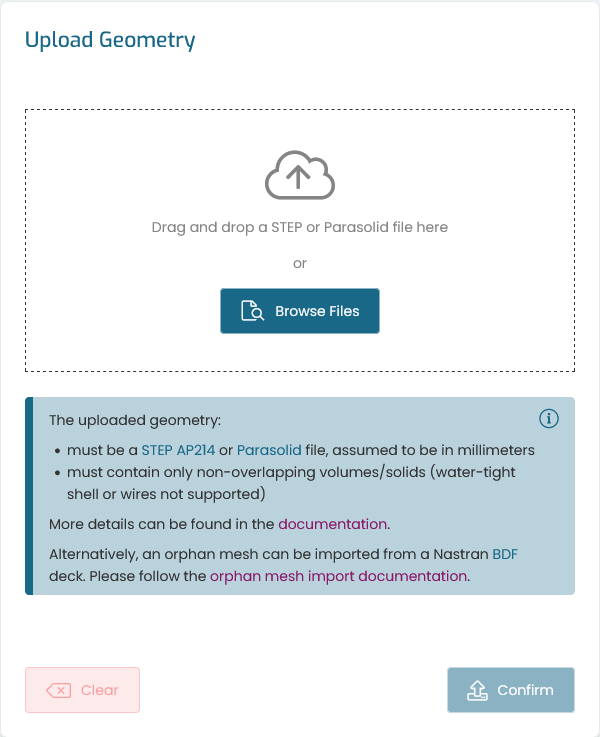
Fig. 3.1 Upload geometry panel
3.2. Orphan mesh import
It is also possible to import geometries described by an orphan mesh.
This feature may allow the import of a problematic geometry, or an integration with other workflows where the original geometry is not available. This, however, will not allow for further edits of the original mesh or existing sets. Refinements during optimization are not affected.
The orphan mesh must, however, be prepared for import and respect the following rules:
Supported orphan file formats are Nastran BDF.
The mesh must contain only TET4 (4-noded tetrahedral) elements.
The mesh must be welded (or conform) across multiple parts (or volumes).
Different volumes must be represented by different material IDs.
Relevant surface sets should be the target of a PLOAD (static pressure load) with a unique magnitude. The distinct magnitudes will be used to differentiate between sets. These may or not match geometry faces as illustrated in the Imported orphan mesh example.
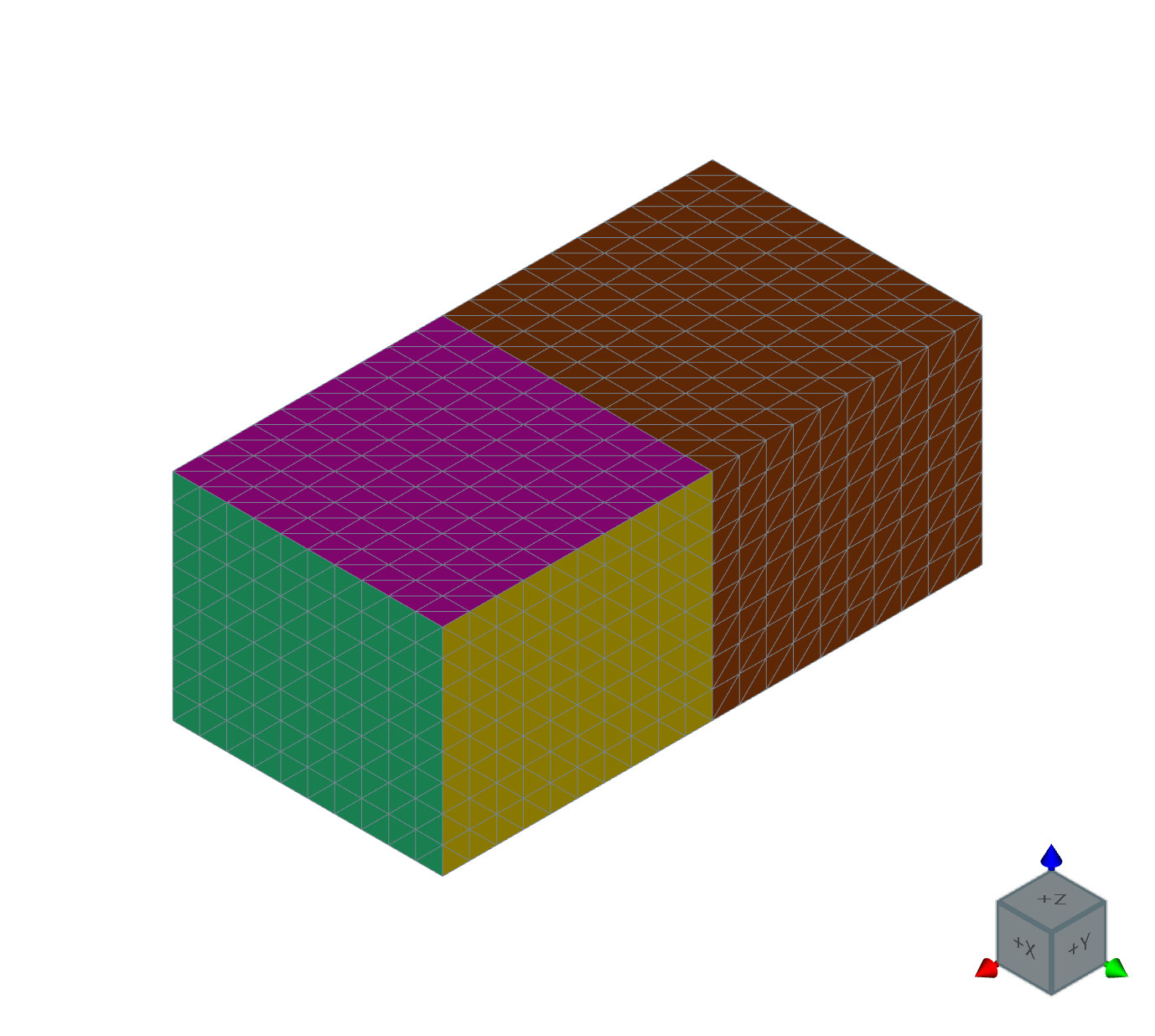
Fig. 3.2 Imported orphan mesh