13. Beams
In finite element analysis, beam elements provide an efficient means to model slender structural members subjected to combined bending, transverse shear, and axial loading along their longitudinal axis. These elements discretize the beam’s neutral axis into a series of straight line segments, each with consistent cross-sectional geometry.
While springs offer simple point-to-point connectivity between reference nodes with user-defined stiffness components, beam elements incorporate full geometric stiffness derived from their cross-sectional properties and material constitution.
The beam elements available in Möbius are formulated using the Timoshenko–Ehrenfest beam theory.
Fig. 13.1 shows an assembly with two beam segments of distinct sections connecting rigid components.
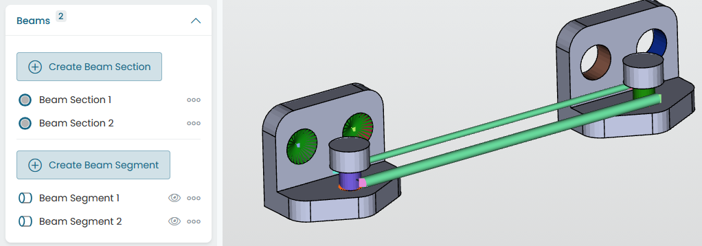
Fig. 13.1 Assembly containing beams.
The same figure also shows the beam section and segment lists, where creation/deletion/clone operations can be started.
13.1. Beam sections
A named beam section defines the circular cross-sectional geometry and references a linear elastic isotropic material. Properties are edited via the context panel as in Fig. 13.2.
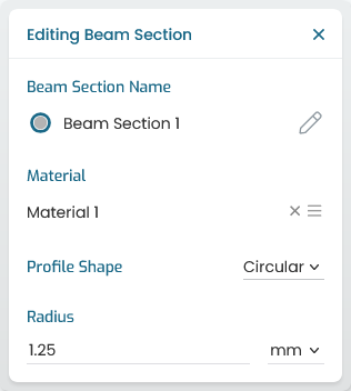
Fig. 13.2 Beam section properties
13.2. Beam segments
A beam segment creates a chain of collinear finite elements between two distinct reference points, inheriting the section geometry and material properties defined above. The available user inputs are presented in Fig. 13.3. The straight path between the given reference points is divided into equal-length elements.
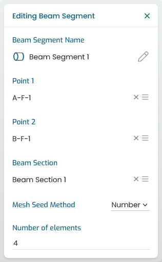
Fig. 13.3 Beam segment definition