8. References
Reference points and coordinate systems serve as fundamental geometric entities that define precise locations, orientations, and local coordinate frameworks essential for applying loads and boundary conditions, and establishing connectivity within assemblies.
The References tree lists existing reference points and coordinate systems, together with buttons and shortcuts for creating, cloning, deleting, or editing these entities.
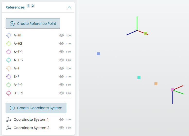
Fig. 8.1 References tree
8.1. Reference points
Reference points are defined by a set of coordinates and a name, as illustrated in Fig. 8.2. The Measure tool can be used to easily create reference points from geometric entities.
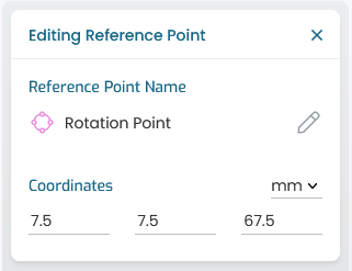
Fig. 8.2 Reference point properties
8.2. Coordinate systems
Coordinate systems provide local reference Cartesian frames that override the global coordinate system for spring elements.
New coordinate systems can be defined as illustrated in Fig. 8.3, with a name, and 3 points:
Origin: defining the coordinate system origin
Point on X: on the positive local X-axis
Point in XY: defining the local Y-axis direction
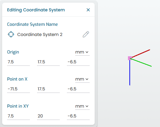
Fig. 8.3 Coordinate system properties
These three points must be distinct and non-collinear to form a valid right-handed orthogonal frame.
Local coordinate systems are rendered with a local triad showing X (red), Y (green), and Z (blue) lines at the origin point, providing clear visual confirmation of orientation in the 3D viewport.